The Pulsar Engineering
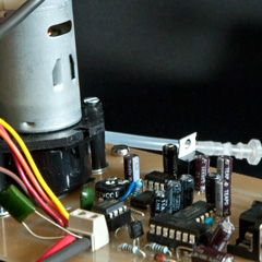

Recently I have bought a small 12V peristaltic pump from a fishkeeping store online. The idea I had was to use it to pump various fluids such as solvents, bases and acids at a precise flowrate. Peristaltic pump are great on that side because they have no mechanical parts in contact with the fluid and you don't have to pressurize anything in order for it to work. It has some down-sides however. For example, it is often required to place a check-valve in the fluid circuit to prevent back flows when the pump stops. Nevertheless, this was a great opportunity to test a few ideas!
After playing a bit with it at various voltage (flow rate can be tuned by changing the voltage which changes the pump rpm), I quickly realized that the thing was actually working but that it was hard to set a wanted flow rate for sure as back-pressure and viscosity were putting a response torque on the DC motor which changed its speed and so the flow rate depending on the operating conditions. This is a big issue because if you are feeding from/to a tank for example, the flow rate will depend on the height of the liquid in your tank because of the back-pressure phenomenon.
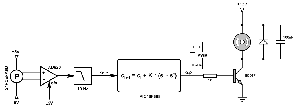
The almost immediate solution was to create a feedback loop to increase or decrease the motor voltage in real-time using the output of a flow sensor. I have used a differential pressure sensor 24PCEFA6D with an AD620ANZ instrumentation amplifier as flow sensor. This kind of flow sensor is not linear but I don't care because all I want is the flow rate to be stable and equal to some fixed value. The output voltage is then read by a PIC16F688 microcontroller and the command is sent to the pump motor by a PWM signal.
Concerning the command ci+1 to apply, I'm using a simple model:

with K a fixed constant and s' the fixed flow rate that we would like to reach. This is nothing but a discrete version of an integrator feedback which has the benefit of having no position error and should be quite stable even if it will be slower to react to changes.
The circuit design I have used is given on Figure 1. It shows the differential pressure sensor with the instrumentation amplifier, a 10 Hz filter and the microcontroller which computes the next command to use knowing the previous command and the sensor state. Finally, the pump motor is driven by a PWM circuit. I had to add a 100 nF capacitor and a diode to prevent EM kickbacks that caused the PIC to reboot every few seconds.
The software was set-up to use the TMR0 as PWM generator (the 16F688 has no PWM output by its own) by incrementing a counter from 1 to 255 every 11 µs. The counter is then compared to the command signal to check if the PWM output should be a 1 or a 0. The TMR1 was used to operate the feedback loop every 500 ms and the value of K was set to 0.1 experimentally. I recommend not reading the sensor data every 500 ms but to read it as fast as possible and to accumulate the results in a temporary register to make an average value that is less prone to noise:
void main(void)
{
	init();

	PEIE = 1;
	GIE = 1;

	unsigned long ulAnalog = 0;
	unsigned long ulNumSamples = 0;

	float fPWM = (float)g_ucPWM;

	while(1)
	{
		/* accumulate sensor data */
		ulAnalog += analog();
		ulNumSamples ++;

		/* set to 1 every 500 ms */
		if(g_bProcess)
		{
			g_bProcess = 0;

			/* get average */
			unsigned short usValue = (unsigned short)(ulAnalog / ulNumSamples);

			/* reset accumulator */
			ulAnalog = 0;
			ulNumSamples = 0;

			if(usTarget == 0)
				g_ucPWM = 0;
			else
			{
				/* control model with K=0.1 */
				float fDelta = (float)g_usTarget - (float)usValue;

				fPWM += 0.10f * fDelta;

				if(fPWM > 255.0f)
					fPWM = 255.0f;
				else if(fPWM < 0.0f)
					fPWM = 0.0f;

				g_ucPWM = (unsigned char)fPWM;
			}
		}
	}
}
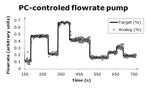
The results were remarkable and the pump is relatively fast to react to change in the desired flow rate with less than 5 sec reaction time. You can see them on Figure 2 with water. The overall signal seems to be stable within a 5-10% error with the desired output and a mean value equal to the target. This is good news because it means that the volume pumped after a sufficiently long time should be perfectly equal to the expected value.
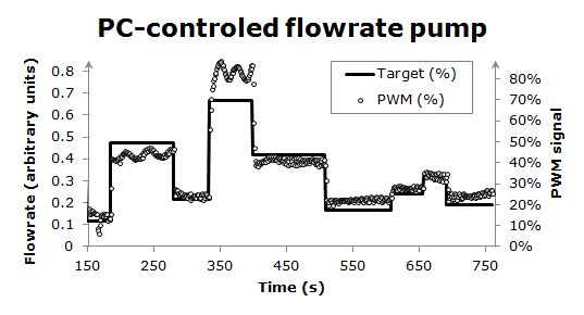
An interesting result can be seen on the PWM command of the system which is given on Figure 3. First, the PWM signal is not strictly proportional to the flow rate (or, at least, the pressure drop recorded by the sensor). Second, there are clear oscillations in the command which might be due to the discrete sampling of the system. I would then suggest increasing the reactivity of the command/sensor if you would like to experiment with this.
Anyway, the circuit performs extremely well and cost less than 100 EUR to build (pump included). The only down side I had was that I broke my pump by clogging it with yeast cultures in another experiment... But I promise, I'll buy a new pump and share the results with you!