The Pulsar Engineering
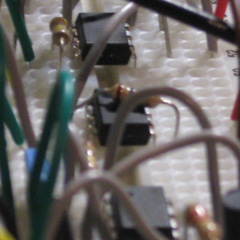

Today I would like to tell you about a chip I have fallen in love with: the TC962 by Microchip. It can be used to create a split power supply from a positive-only one. So, if your circuit has only a +9V battery and you require a symmetric -9V/+9V supply for op-amp or other parts, you can use to the TC962. I almost forgot to tell you: they are free for students! Just log-in to the Microchip sample platform and order a few ones.
Of course, there are many ways to get split power supplies. Other solutions such as virtual grounds, two-battery systems... will not be discussed here as I would like to focus on the voltage inverter.
The classical usage of the TC962 is given on Figure 1 but you may also add them in parallel to increase the available load, such as on Figure 2.
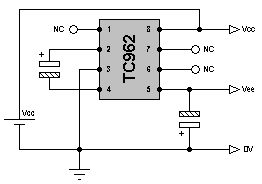
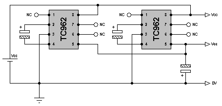
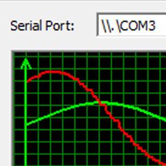
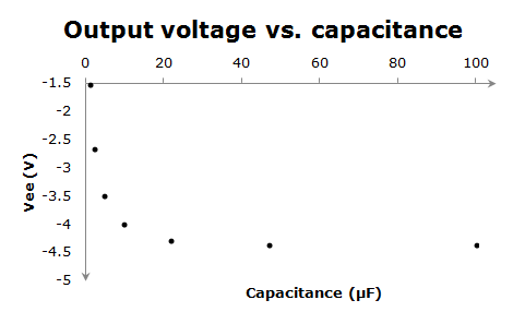
From the two Figures, we can see that two types of capacitance are required for the circuit. The first one is used by the chip to invert the voltage and is connected between the pin 2 and 4. The effect of the capacitance is shown on Figure 3 for a +5V supply. There is a clear exponential behaviour and the final output voltage (not strictly equal to the inverse of the positive supply) seems to be reached with a 22 µF capacitor. I recommend not using smaller capacitances since the output voltage would quickly decrease.
The second capacitance is used to store the charge created by the pumping device and is placed at the output on pin 5. Omitting this capacitance will result in failure of the split power supply design. From experience, I would recommend using a 100 µF capacitor although a 10 µF one already gives good results.
Finally, I haven't talk about the load capacity of these devices. On Figure 4 I show the results of an experiment where I have used variable load (using several resistors). Clearly, we can draw up to 100 mA from one chip but this will be at the cost of the output voltage. There are no strict recommendations on the maximum load to draw from the negative supply since the output voltage will immediately begin to drop.
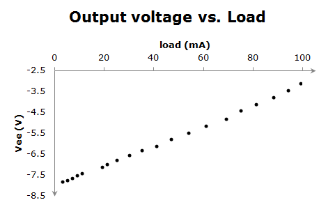
Still, we can do some maths for a given circuit. For example, when we are using op-amp for signals in the -5V...+5V range, we would like to have a load such that the negative supply will allow travel over the whole range. Because some op-amps have trash-voltage, we should increase the boundary by an equivalent value. When using a LM833N for instance, the trash voltage is about 1.5V so to study signals in the -5V...+5V range we should have a power supply of, at least, -6.5V/+6.5V. The positive side is not much of a problem (we are happy with a 9V battery) but the negative side will depend on the load. From the previous graph (you should always check that assumption for your own circuits!), I can tell that with my +9V supply, I can draw a maximum 40 mA. Because the LM833N have a maximum 8 mA consumption (from the datasheet), I know that I need one TC962 per 5 LM833N dual op-amps.
If you require more current, simply use more TC962 such as on Figure 2. Easy isn't it?